Welcome to SALES
RESISTANCE

INDUCTION

GENERAL

PROGRAMMERS
6 Channel Automatic P256 Programmer/Controller
During the heat treatment process it is vital that the temperature can be controlled accurately.
HTC offers a range of programmers to suit the individual requirements of the end user whether working under site conditions or in a workshop.
Each control channel can either be operated for manual temperature control of the workpiece, or in automatic mode.
In automatic mode, the channel controller will ensure that the control zone temperature closely follows the temperature rise, hold and fall and hold period parameters programmed by the operator.
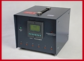
TEMPERATURE RECORDER
ANALOGUE CHINO RECORDER 12 CHANNELS
Temperature recording is a vital part of the heat treatment cycle for both preheating and post weld heat treatment. The standard temperature recorder offered by HTC is the Chino EH Series. The unit is incased in a mild steel box and a handle is fitted for ease of movement. On the rear of the unit 12 thermocouple sockets are fitted to enable the unit to be connected by the widely used type k thermocouple.
The standard features of this unit are:-
- Temperature range of 0-1200 Degrees Celsius.
- 12 Type K thermocouple sockets
- 110 Volt /240 Volt 50HZ Supply Voltage
- Chart Width 180mm
- Chart Speed Variable in Steps from 12.5mm, 25mm,50mm, 100mm and continuous

DIGITAL CHINO RECORDER 12 CHANNELS
The digital recorder has a number of useful features to supplement the robust features of the analogue version and these follow. The hybrid recorder is a 180mm multi-point type having 12 channels and provides a simultaneous display of multi-channel data, universal sensor input with alarm display and printing options. Packages for data processing for use with the recorder are available.
DIGITAL RECORDER SPECIFICATION
| Overall dimensions | 360mm W x 360mm H x 445mm L | Types of thermocouple | Selectable, set for Type K |
| Weight (cased) | 18.5 kg | Chart Width | 180mm |
| Scale length | 180mm | Channels | 12 |
| Accuracy | ±0.1% input span | Stamping interval | 10 seconds |
| Balancing time | 2 seconds | Ambient temperature | 0°C to +40°C |
| Input Voltage | 100-240V A.C., 50/60 Hz | Temperature range | 0-1200 Degrees Celsius |

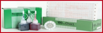
TEMPERATURE RECORDER ACCESSORIES
| CEH-002 | Ink (12 Colors) for Chino recorder E100-12. |
| CEH-003 | Drive Cord 12pt for Chino recorder E100-12. |
| CEH-004 | Chart Paper (Chino recorder). |
| FFR-001 | Fuji Digital Recorder 12 Channels. |
| FFR-002 | Recorder Print Head Cartridge. For 12 point Fuji temperature chart recorder. |
| FFR-003 | Chart Paper (Fuji recorder) |
CABLES AND WIRES
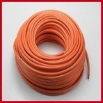
| DIC-001 | 16mm² HOFR Double Insulated Cooper Cable - 100m. |
| DIC-002 | 25mm² HOFR copper, 185A, Triple cable set. |
| DIC-003 | 3-way splitter c/w 3x60A female & 1x300A male connectors. |
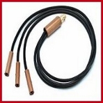
| TCK-003 | 2m ‘jumper’ compensating lead fitted with two type K thermocouple plugs. |
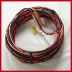
| DIC-004 | 60 Volt Heater wire c/w NI CH 212 cold tails welded to each end. |
| DIC-005 | Ni-Ch 80/20 -19St Heater Core Wire. |
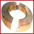
| CPS-013 | Copper shim 300 Amp-19mm wide. |
| CPS-014 | Copper shim 60 Amp-12.7mm wide. |
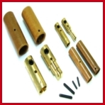
CAMLOCK CONNECTOR & SLEEVE
| CPS-001 | 300 Amp Female Sleeve. |
| CPS-002 | 300 Amp Female Brass Camlock Connector. |
| CPS-003 | 300 Amp Male Sleeve. |
| CPS-004 | 300 Amp Male Brass Camlock Connector. |
| CPS-005 | 300 Amp Fiber Pins. |
| CPS-006 | 60 Amp Female Sleeve. |
| CPS-007 | 60 Amp Female Brass Camlock Connector. |
| CPS-008 | 60 Amp Male Sleeve. |
| CPS-009 | 60 Amp Male Brass Camlock Connector. |
| CPS-010 | 60 Amp Fiber Pins. |
| CPS-011 | Fixed and moving contacts for 200A contactor. |
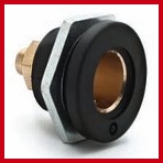
| CPS-012 | 300A female panel mounted camlok connector. |

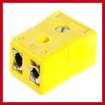
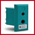
CONNECTOR AND PLUGS
| TCK-004 | Type K,Panel mounted thermocouple socket. |
| TCK-006 | Connector, TC Type k, 2-Pin Male (Thermocouple Plug in line). |
| TCK-007 | Connector, TC Type k, 2-Pin Female (Thermocouple Socket in line). |
| PLP-001 | 110V, 16A, 3-pin in-line plug. |
| PLP-002 | 110 A.C panel mounted outlet |


INSULATION SPARES & ACCESSORIES
| CFB-001 | Ceramic Fiber Blanket up to 1260ºC. 128kg/m3 (25mm thick unmeshed roll 7320mm x 610mm). |
| CFB-002 | Roll stainless steel mesh for insulation mat, 635mm wide, 25 kg/roll. |
| CFB-003 | Roll stainless steel mesh for insulation mat, 330mm wide, 15 kg/roll. |
| CFB-004 | 25mm thick s/s meshed mat 600mm x 1800mm. |
| CFB-005 | 25mm thick s/s meshed mat 300mm x 1800mm. |
| CFB-006 | 25mm thick s/s meshed mat 600mm x 900mm. |


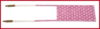
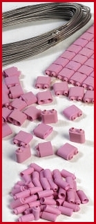
CERAMIC PAD ELEMENTS
| HEC-013 | Main body beads. |
| HEC-014 | Main body beads with hole. |
| HEC-015 | Finisher beads (Male End Beads) |
| HEC-016 | Starter beads (Female End Beads) |
| HEC-017 | Tail Bead, Pink |
| HEC-018 | Tail Bead, Wait |
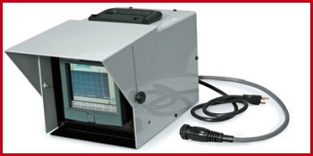
DIGITAL RECORDERS
Digital Recorder A6100 – 6 Channels
The digital recorder is commonly used in stress relieving and critical preheat applications.
The recorder stores temperature data based on time. It is not required to perform successful
heating applications.
- The recorder is attached to power source top panel or can be removed for office downloads, storage or protection when not in use.
- The recorder power cord plugs into the 110 V auxiliary receptacle on the rear of the ProHeat and the TC cable plugs into the TC receptacle on the rear of the ProHeat.
- Six or twelve temperature (0 –10 V) inputs provide temperature data on the heating cycle.
- The recorder is equipped with a touch screen for simple programming and use. The color display permits clear monitoring of the heating process in outdoor environment (direct sunlight).
- Data can be transferred from internal memory to USB memory stick or directly to a PC via a network cable for printing, storage or further analysis. Files are encrypted for quality assurance.
- Simplified software prints recorded information onto 8-1/2 x 11 in size paper for convenient handling.
- The recorder does not require pens, paper or fragile mechanical devices to document the heating cycle.
Dimensions Shipping Weight
| Height | 14 in (356 mm) 22 lb (10 kg) |
| Width | 12 in (305 mm) |
| Dimension | 18 in (457 mm) |
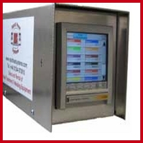
Digital Recorder RHS – 18 Channels
The Rapid Recorder offers unrivalled input accuracy with a 125ms total sample
rate for 18 channels. The input channels are configurable to suit the process requirements.
The recorder has a touch screen display for simple programming and use. The colour
display enables operators to clearly monitor the heating process in outdoor
environment (direct sunlight).
They all have onboard Flash data storage capability, Ethernet communication and
Compact Flash. Data is stored in tamper resistance binary format that can be
used for secure, long term records of the process. The rapid recorder is easy and intuitive
to use ensuring faster productivity and minimal learning requirements. It also
incorporates a ‘Pop Up’ full ‘QWERTY’ keyboard to facilitate easy data or message entry.
There are no complicated button presses.
- Data can be transferred from internal memory to USB stick or directly to a PCvia a network cable for printing, storage or further analysis using Review/ Quickchart Lite Software
- Files are encrypted for quality assurance
- Simplified software prints recorded information onto A4 paper for convenient handling.
- The recorder does not require pens, paper or fragile mechanical devices to document the heating cycle.
CABLES
OUTPUT EXTENSION CABLES RHS 35
The output extension cables are available to remote the power source up to 50 feet from the work. Insulated quick-connects are used to easily remove and attach the coolant lines. The power source connector
securely locks the cable to the power source and insulates the output connector. The Cable Identification System built into the connector identifies the liquid-cooled systems and permits full power. The cables are flexible for ease of use.
| HTC-O10f | Output Extension Cable 10 Ft = 3 M |
| HTC-O25f | Output Extension Cable 25 Ft = 7.6 M |
| HTC-O50f | Output Extension Cable 50 Ft = 15.2 M |
| HTC-O75f | Output Extension Cable 75 Ft = 22.8 M |

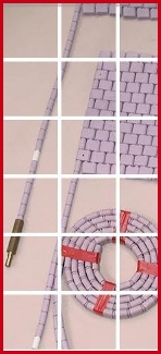
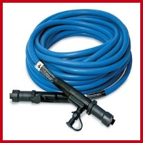
LIQUID-COOLED HEATING CABLE
The liquid-cooled heating cable couples the power to the part to be heated. The silicone hose encloses a special copper conductor specifically designed for carrying high-frequency current to maximize efficiency. The hose also carries the coolant, which cools the conducting wire. The hose is reinforced for strength and durability.
| HTC-H30f | Induction Heating Cable 30ft = 9.1 m |
| HTC-H50f | Induction Heating Cable 50 Ft = 15.2 M |
| HTC-H80f | Induction Heating Cable 80 ft = 24.4 m |
| HTC-H140f | Induction Heating Cable 140 ft = 42.7 m |
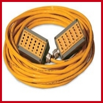
TC EXTENSION CABLES
The thermocouple extension cable is a simple means of provided thermocouple inputs from the heated part to the power source. The durable 50ft cable eliminates the cluttered stringing of individual wires to
the work. The terminal connection enables six thermocouples to be used with the system.
| HTC-EX 50 | Extension Cable 50 Ft = 15.2 M |
| HTC-EX 75 | Extension Cable 75 Ft = 22.8 M |
COVER SLEEVE & PREHEAT COVER
PREHEAT CABLE COVERS
Preheat cable covers are available to protect the heating cable from slag and molten metal created during welding. The preheat covers are easy to install and can withstand temperatures up to 650°F (343°C).
| HTC-C30f | Cover Sleeve 30ft = 9.1 m |
| HTC-C50f | Cover Sleeve 50 Ft = 15.2 M |
| HTC-C80f | Cover Sleeve 80 ft = 24.4 m |
| HTC-C140f | Cover Sleeve 140 ft = 42.7 m |

PREHEAT INSULATION
The insulation is designed to insulate the work for process efficiency, maintain the optimum coupling distance between the coil and the work and protect the liquid-cooled cable from high temperatures.
Preheat insulation is provided in strips six or twelve inches wide and ten feet long. Preheat insulation is 1/2 in (12.7 mm) thick due to the lower temperatures of preheating (typically up to 600°F). The insulation is cut to length for the application.
| HTC-P006 | preheat insulation 6 Inches. |
| HTC-P012 | preheat insulation 12 Inches. |

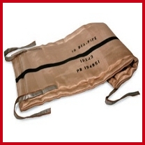
POST WELD HEAT TREATMENT INSULATION BLANKETS
are sized and stenciled for the pipe size to be treated. The insulation is sewn into a silica blanket, which provides high durability. 50 thermal cycles or more can be achieved with one blanket. The sewn blanket
insulation does not create the dust and particulate associated with insulation. This creates a friendlier environment for the heat-treaters.
| HTC-IPWHT20 | Post Weld Heat Treatment Insulation Blanket For 20 in pipe (24" x 73") |
| HTC-IPWHT32 | Post Weld Heat Treatment Insulation Blanket For 32 in pipe (24" x 112") |
Also you can order your requirement for any pipe sizes …

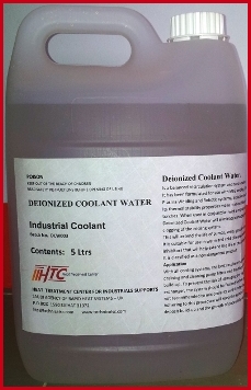
DEIONIZED COOLANT WATER
It has been formulated for use with MIG welding, TIG welding, Laser Welding, Laser cutting,
Plasma Welding and Robotic systems, Induction machine. Its thermal stability properties make it an excellent choice for use with higher performance torches. When used in conjunction with a regular coolant system maintenance program,
Deionized Coolant Water will eliminate damaging mineral deposit build up and will prevent clogging of the cooling system. This will extend the life of pumps, seals, gaskets and prevent costly downtime. It is suitable for use in warm and cold climate conditions. It contains rust and corrosion inhibitors that will help extend the life of the cooling system components. It is classified as a non-dangerous product
Application
With all cooling systems, the best results are achieved by changing the coolant annually, draining and cleaning pump filters and flushing the tank to remove any sludge or solids build-up. To prevent the risk of damaging any high efficiency radiator type circulator/heat exchanger, the system should be flushed before adding new coolant in to the system. It is not recommended to mix coolants as this may also invalidate the manufacturer’s warranty. Adhering to this procedure will keep the system free from the hazards of damaging mineral deposit build-up and the growth of potentially dangerous bacteria.
| HTC-DCW001 | Deionized Coolant Water 5 Ltrs |
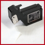
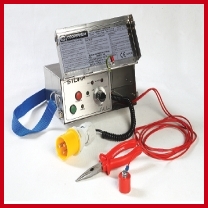
THERMOCOUPLE ATTACHMENT UNIT
Accurate temperature measurement is ensured by the attachment of thermocouple conductor wires directly to the metal surface by a spark discharge welding system. Accordingly, the metal surface becomes the
hot junction of the thermocouple, so eliminating any inaccuracy associated with direct heat transfer from the heating source. After the wires are removed from the metal surface, it is usually necessary only to lightly
dress the local area. The standard unit is operated from a rechargeable battery – several hundred welds can be made before a re-charge becomes necessary using the 110V AC or 220V connection to the heat treatment transformer.
The unit operates at a safe low voltage.
OPERATION OF THERMOCOUPLE WELDING UNITS
- Remove loose scale or rust by wire brushing or other suitable means.
- Dress a small area no more than 100mm from attachment point to bright metal for return magnet.
- Set the output to approx 80% of maximum output.
- Push back insulation on thermocouples conductor wire to expose 5mm of bare wire.
- Grip conductor wire 4mm from wire end with pliers &firmly touch wire end to attachment point at 90°
- Press discharge button.
- Gently bend wire through 90° 3-4mm above surface. If weld is sound, repeat for second conductor wire.
- Welds to be approx 5mm apart.
Or by auto, Direct attachment of thermocouples to the work-piece by the ‘capacitive discharge method’ has long been established as the preferred industry standard method of attaining accurate temperature measurement of the work piece being heat-treated or monitored.
SPECIFICATIONS
| Dimensions | 180Hx289Wx95mmD | Weight | 4kg |
| Charge Voltage | 110 or 240V a.c | T/couple types | Type K |
| Standard Wire size | 0.711mm dia | Power Consumption | 5.0 VA |
| Battery Voltage | 12 Volts | Battery Capacity | 2.7 Ah |
| Battery Monitor | Monitoring LED and Automatic Full Discharge Protection |
| TAU-110 | Thermocouple Attachment Unit 110v |
| TAU-220 | Thermocouple Attachment Unit 220v |
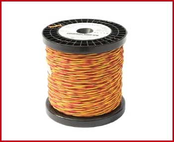
THERMOCOUPLE WIRE K TYPE
Accurate temperature measurement is ensured by the attachment of Type K nickel chrome/nickel aluminium thermocouple wire, insulated with high Temperature glass braid. Recommended maximum temperature 800ºC.
A consumable item, which is used to convert the thermal energy at the hot junction of the thermocouple to an electrical mV signal which can then be used by temperature control and recording instruments to accurately
record and control the temperature of the item being heat treated. Conforms to:
BS EN 60584-1 : 1996 part 4
BS EN 60584-2 : 1993 class 1 and ANSI-MC96
The thermocouple wire is attached directly to the work piece using the ‘thermocouple attachment unit’ Heat Treatment Center.
| TCK-001 | TC wire K Type - 0.711mm Diameter Double Insulated. 100m Roll (Yellow & Read). |
EXTENSION WIRE K TYPE
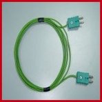
Suitable for use with type K thermocouples where monitoring thermocouples, in addition to the control thermocouples, are required for temperature monitoring purposes. Available in 30m lengths complete with type K thermocouple plug and socket or in 100m rolls without plug and socket (plugs and sockets can be supplied
separately as required).
| TCK-002 | Thermocouple compensating cable - 100m/roll |

BANDING MACHINE
For tightening, cutting off and clipping mild and stainless steel banding. For bands of more than four heating elements, HTC recommends that mild steel banding and banding clips are used to ensure the heaters remain in full contact with the pipe.
For temperatures in excess of 650ºC we recommend using stainless steel
banding and clips.
| BMS-001 | Stainless steel Banding machines. |
| BMS-002 | Stainless steel banding 1/2” - (30m roll). |
| BMS-003 | Stainless steel banding clips 1/2” - (box of 100). |

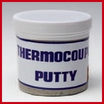
THERMOCOUPLE PUTTY
A small portion of the soft putty is fixed over the hot junction of the thermocouple, which is attached to the item being heat-treated. Once the putty dries, after 20 minutes, it hardens to protect the hot junction and helps avoid possible short circuit of the thermocouple wires which would result in temperature control
and recording errors.
| TCK-008 | Thermocouple putty 0.5 k.g (0.5 kg jar of high temperature cement). |
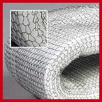
CERAMIC FIBER BLANKET
In modern furnace technology ceramic fibre mats are essential for lining the interior of all types of industrial furnaces. They are also particularly suitable for the insulation of local
heat treatment spots. With a thickness of 25 mm they protect the heating elements against sintering rockwool as first cover beneath the rockwool.
| CFB-004 | 25mm thick s/s meshed mat 600mm x 1800mm. |
| CFB-005 | 25mm thick s/s meshed mat 300mm x 1800mm. |
| CFB-006 | 25mm thick s/s meshed mat 600mm x 900mm. |
| CFB-001 | Ceramic Fiber Blanket up to 1260ºC. 128kg/m3 (25mm thick unmeshed roll 7320mm x 610mm). |

CONNECTOR, TC TYPE K, 2-PIN
| TCK-006 | Connector, TC Type k, 2-Pin Male (Thermocouple Plug in line). |
| TCK-007 | Connector, TC Type k, 2-Pin Female (Thermocouple Socket in line). |


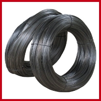
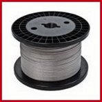
SOFT IRON WIRE
For heating element bands of less than four heating elements, soft iron wire is adequate to fix the heating elements and insulation around the work piece.
| BMS-004 | Soft iron wire. (CS-SS). Iron wire is adequate to fix the heating elements and insulation around the work piece. |